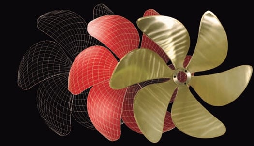
PERFECT PITCH: Choosing the right prop requires some trade-offs between diameter and pitch; hand; number of blades; blade area, section, skew and rakeand more.
Since well before 1800, various mechanisms have been developed to propel a boat, including the paddlewheel, adapted from the waterwheel then in common use, and the screw propeller. From the outset it was clear that it would be necessary to specifically match a propeller to the driving engine to obtain the greatest thrust per horsepower. Understanding this need led to the rapid development and patenting, prior to 1840, of props with widely differing blade shapes and configurations, including variable pitch, controllable pitch and contra-rotating blades. Ongoing efforts to improve prop performance have accelerated in recent years with the development of new design tools (often adapted from jet engine design efforts) and new materials and methods of production.
The selection of a propeller for a particular boat is typically a multistep process involving numerous trade-offs. A simple specification of prop diameter and pitch, for example, 18 by 16 inches, three blade (the first number is prop diameter, the second designates pitch) is only a starting point. A prop specification will include “hand (left or right, the rotation direction), diameter, pitch, number of blades, blade area, blade section (ogival or airfoil), blade skew and rake, “cup and the dimensions of the prop shaft on which it will be installed. Props for sailboats may allow manual adjustment of blade pitch or provide automatic pitch adjustment. Feathering props are popular, especially among sailors who race their boats. Controllable-pitch feathering props are increasingly common on large sailboats, along with non-feathering controllable pitch props installed on many motoryachts.
Most propellers are designed to operate with the smoothest possible flow of water across the surface of the blades. However, in practice, propellers may experience ventilation, in which air is pulled into the blades from the surface of the water, or cavitation, an operating condition frequently confused with ventilation. Operating the prop too close to the surface of the water is a common cause of ventilation and is likely to be seen more in outboard and stern drive installations than in conventional inboard shaft-driven boats. Cavitation, most often caused by high-power loading (hp/prop area) and/or excessive propeller speed, creates areas of extremely low pressure on the back side of the prop blades (the side toward the front of the boat). The pressure may become low enough to cause the formation of bubbles. The force imposed on the blades by the imploding bubbles can create vibration and lower the efficiency of the prop. Over time, the energy released in the collapse of these bubbles can even be sufficient to erode bits of metal from the blade surface. Although both propeller ventilation and cavitation are normally considered undesirable, both of these effects are used to advantage in propellers specially designed for high-speed boats.
Most of the propellers used on conventional inboard engine-driven boats-sailboats, express cruisers and motoryachts-are made of either bronze or stainless steel alloys. The very large market for props used on outboard motors and sterndrives encourages experimentation that has led to the development of more radical designs. Props for this market are often made of aluminum and stainless steel, as well as high-strength aerospace composites and plastics.
Some of these latest outboard and sterndrive props have removable, interchangeable blades. The design allows quick replacement of a damaged blade and adjustment of blade pitch over a range of several inches, as well as easy exchange of one set of blades for another set that has the pitch needed to optimize performance under varying altitude and temperature conditions. Michigan’s “Vortex propellers separate the propeller hub from the blade assembly, allowing interchange of the working part of the prop to meet varying operating conditions and reducing the cost of prop replacement in the event of damage. In addition, propellers with integrated blade tips within a surrounding ring are now available for use on outboards. Developed by RingProp of Melbourne, Australia, these can claim performance advantages from increased lift, a reduced tendency to cavitate in turns and, because of the surrounding ring, reduced likelihood of people being injured by contact with prop blades.
Regardless of the type or size of the propeller, its job is to convert the energy available from the engine into the thrust that will force the boat through the water. The fixed-pitch prop on a boat must allow the boat engine’s wide-open throttle rpm to reach the maximum specified by the manufacturer, plus about 50 to 100 rpm when the boat is carrying its normal load and the hull and running gear are totally clean. The process of selecting a prop that will meet all these criteria is commonly called “propping.
When additional high-speed performance is required, the shape of the prop blade may be altered from the norm by adding curvature to the trailing edge of the blade, extending from near the root out to, and sometimes close to, the tip. The degree of additional curvature is usually defined by an almost dimensionless reference-the “cup number. The dimensions of cups have been standardized and defined by Michigan Wheel Engineering, one of the leading recreational vessel prop manufacturers. Its standard establishes 12 gauges of cup, each representing 0.015 inch of additional curvature of the trailing edge of the prop blade. Adding cup to the prop may also improve reverse thrust.
Choosing the optimum prop for planing hull boats, especially those designed to cruise at speeds beyond about 30 to 35 knots, is more complicated. The higher power available from the engines in fast boats places special demands on the propeller. The design of the boat’s running gear usually rules out the use of conventional propellers large enough to absorb the engine power. It may be necessary to choose a fully cavitating propeller. Props for this application may have to be designed with additional, often more radically shaped blades and be made of very high-strength alloys.
The designers of many boats, especially those specializing in planing hull recreational vessels, usually want to limit the boat’s draft in an effort to minimize the diameter of the prop and its projection beneath the hull. In many designs the prop is partly housed in a tunnel, a concave section of the hull. Designers sometimes also reduce the prop’s diameter, but there is a limit to how far they can proceed before efficiency drops to an unacceptable level. Reducing prop diameter increases the amount of power that must be absorbed by each square inch of prop area and can lead to cavitation and a waste of energy consumed in imparting a swirling motion to the water expelled from the propeller.
An early solution to this problem was seen in 1877 with the use of contra-rotating props on a torpedo (where the reduction in swirl loss also reduced steering problems). In contra-rotating drives it is common for the aft prop, which is operating in water that is moving faster than the forward prop, to be of smaller diameter and have more blades, usually with greater pitch than the forward set. (Contra-rotating props also have been used occasionally on aircraft, such as the Russian Bear bomber and the British Seafire.)
High-speed boats may be equipped with supercavitating or fully cavitating props, recognizable by their curved, scimitar-shaped blades. An alternate means for achieving very high speeds is the use of surface-piercing propellers that operate with only half of the prop’s diameter immersed in the water. These props operate fully ventilated, with the induced air protecting the blades from the detrimental effects of cavitation. The surface propeller concept is very highly developed in the Arneson Drive that incorporates both adjustable propeller immersion and vectored thrust for steering. This type of drive is particularly attractive at speeds above 40 knots where the drag of conventional running gear would otherwise become a major consideration. These surface-piercing drives are in use today on vessels ranging from about 30 to 200 feet in length.
Many Arneson drives use Rolla propellers. The Rolla props are manufactured of NiBrAl alloy in sizes from 28 to 65 inches in diameter, suitable for use with engines delivering 600 to 4,000 hp. Stainless steel Rolla props are available in sizes from 16 to 32.5 inches and are suitable for engine power from 250 to 1,400 hp. (Rolla also produces fully submerged props in NiBrAl alloy in sizes from 28 to 75 inches for use with engine power ranging from 600 to 4,000 hp.)
It may seem that propeller designers have explored most of the opportunities for improvement in the past 200 years. However, recent advances in understanding fluid flow in jet engines for high-speed aircraft and in making virtually noiseless props for submarines have created numerous new techniques and a vast pool of information and advanced manufacturing techniques applicable to the design of propellers for boats and yachts. The best is very likely yet to come.
For additional information, contact: National Marine Propeller Association, www.nmpa.net/manufacturers_associates.asp.

